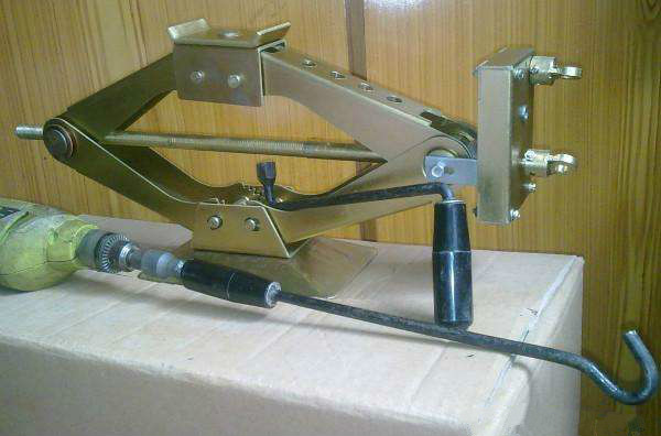
Scissor Jack is a little on-board and handful tool,which is a neccessity for cars on trip, travel and long journey.
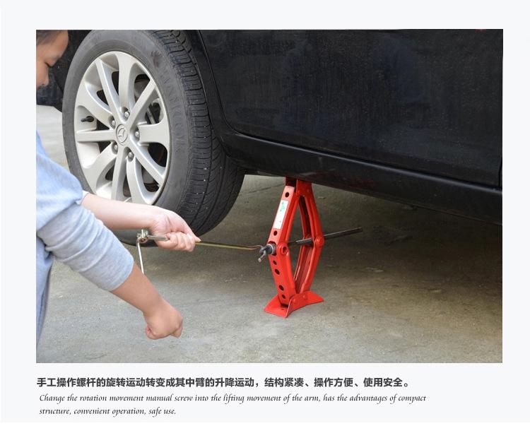
Scissor jack can be used at any time when a flat tire needs to be changed or repaired.
Scissor jack is easy to lift up the car by rotating the screw rod for circles.
About us
Contact us
Scissor Jack Scissor Jack,Mini Scissor Jack,Scissor Car Jack,Car Lift Jack Hebei Liston Lifting Rigging Manufacturing Co., Ltd. , https://www.liftingriggingfactory.com
Based on the /characteristic map, the design of the extended speed range type continuously variable transmission is bookmark0 Gui Naiqi, He Zhemin, Zhang Shi'an book1 (Department of Mechanical Engineering, Hunan University of Arts and Sciences, Hunan Changde 415000), and the table can determine the power flow pattern. In addition, the method of finding the intersection of the characteristic line of the planetary gear train of the J straight line and the f straight 1 is used, and the power flow type is directly determined by the intersection point according to the figure. Taking a wide-speed step-type stepless speed changer with an extended 1.1/characteristic map as an example, the design and power flow analysis were carried out with these “characteristic mapsâ€.
Speed ​​machine; design closed planetary gear train has the advantages of small volume, wide speed ratio range and large transmission power. Incorporating a continuously variable transmission into its closed mechanism can form a variety of control differential gear stepless speed changers such as an extended speed range type and a precision speed control type. Its structural block diagram is as shown. In the figure, n denotes a differential gear train (original mechanism); R denotes a continuously variable transmission; B denotes a fixed axle train.
The three basic members of the differential gear train n are 1, 2, and 3, and their angular velocities are called, "2, "3, the relative angular velocity ratio of the stone 3, the vertical: j23 =. The formula is more and more complicated. It is now a new method for designing and power flow analysis by using the J-characteristic diagram. It is simpler and can be designed according to different known conditions. It can also be programmed and applied to the computer for design. In this paper, an example of an extended speed range type continuously variable transmission is applied to design this method.
According to this, one can be the abscissa (X axis), and one is the ordinate (7 axes). The straight line "i23 is the slope of the line / i23 is the intercept of the line on the 7 axis. It can be seen that when called =W2=W3, the second formula of equation (1) is always true, that is, the straight beam must pass through the (1,1) point. The relationship between this coordinate system and the straight line is called "J characteristic map". Such as.
/ The line between the straight line and the X-axis intersection point (xc, 0) is: / The straight line indicates the relationship between the angular velocity ratios of the three basic members of the differential gear train n as the original mechanism.
The basic member angular velocity of the differential gear train n is set to q and ffl2, and the unsealed basic member of the differential gear train is set as the reference member 3, and the angular velocity is ffl3. Thus, a linear relationship between q and "2" can be obtained. This relationship is the same as the linear relationship between the two, and is also drawn on the /characteristic map, and the straight line of the origin is obtained, = 721. The straight line indicates the constraint of the closed mechanism to the original mechanism, and =, on, / straight line and (direct intersection, that is, the working point of the closed planetary gear transmission. The coordinates are. If there is a stepless speed change R in the closed mechanism, Then the work point will move on / line.
1.4 The heart line takes the same coordinate scale as the above characteristic chart, but the abscissa is changed (the variable is q, and the ordinate (7) variable is ffl4 (see, the position of the end point 4 is in the fixed-axis wheel train B and the continuously variable shifting Between the machines R), or the variable of the abscissa is arbitrarily, the variable of the ordinate is the "714 line" of the transmission ratio 714= of the fixed-shaft train B, which can be modeled by a straight line drawing. .
If the 7th line (slope is) reference line takes 7=1 as the “reference lineâ€, the abscissa value of the intersection of the 714 line and the “reference line†is X=y14. If the angle A is taken as shown, then The above characteristic map has the same coordinate scale, but the variable of the ordinate is the speed ratio r= of the continuously variable transmission R, and the speed range of the continuously variable transmission R is rmr, then the two horizontal lines 7=rm and 7=r The interval between the two represents the shift range of R as shown.
In the shift range of R, m~ can be obtained from rm~rn, and vice versa, as shown. Then, the intersection of the x = line and the reference line of 7 = 1 and the line of the origin is a line, and x = (the line connecting the line with the line of 7 = 1 and the line of the origin is a line.
1.6 Power Partition Coefficient and Power Flow Classification The ratio of the power of the two basic components 1 and 2 that are enclosed in the train to the A is called the power distribution coefficient. According to the force analysis, the planetary gear transmission can be obtained without any friction loss. The general relationship between the torques M between the basic components is calculated according to the calculation formula of the relative angular velocity ratio j23Pj3: the power flow analysis according to the formula (4) is as follows: when Pf>, the symbols of the numerator and the denominator are the same, then the molecule The power represented by the denominator is the same as the input power or the same output power. The power symbol of terminal 3 is opposite to the power sign of terminals 1, 2. Therefore, in a closed circuit, power flows from 3 or V to achieve power splitting. Such a mechanism is called the power split type planetary gear mechanism *2, and the power flow direction is opposite, and there is always one of the terminals 1 and 2 having the same power as the terminal 3. And the power different from the terminal 3 must be greater than the power of the terminal 3. Therefore, in the closed circuit, there is circulating power. Such a mechanism is called a power cycle type planetary gear mechanism.
Based on the above analysis, the subdivision can be obtained. Table 1. Power distribution coefficient Pf Power flow pattern code Input power combined output power combined type Table 1 Power flow classification Because (2) can be rewritten as / straight beam equation: And (4) can be written as /F: then, from the above two formulas y = x, the "value line" can be obtained accordingly.
According to the formula (5), according to the four kinds of “power flow pattern codes†corresponding to different Pf values ​​shown in Table 1 : %, a., and Y, on the book plane, the first should be to find the “demarcation lineâ€. XV-x= is “zero value lineâ€; from y-xv= area, it is not easy to distinguish clearly. Now the area with x> 1, j<0 is taken as an example: Pf is negative.
Bu noisy|=||Noisy|Bu||, so |Pf| <0, when Pf is greater than 1 >1, Pf is a negative value whose absolute value is less than 1, and this area is the evening area.
With power analysis, it is very convenient to perform power flow analysis.
For example, the point shown in the zone is a design example of a P2>1 power 2 extended speed range type continuously variable transmission. It is known that the PX type controlled differential continuously variable transmission shown is a belt type continuously variable transmission. It is combined with the fixed axle train and the differential gear train, and it is required to realize the zero-speed expansion speed regulation range speed regulation. The input speed is "1=1370r/min, the output shaft is the tie rod H of the differential gear train, and its rotation speed is =-289.340122.43r/min. The steering is reversed from "1 to zero and then the same as "1." The number of teeth of the sun gear 1 in the differential gear train is 22=22, the number of teeth of the inner ring gear 3 is Z3=94; the gear ratio of the fixed axle train is =1; the transmission ratio of the belt-type continuously variable transmission is 0.52. The number of teeth of the axle train a is Z4 and 厶, and power flow analysis is performed on this PX type continuously variable transmission.
Solution: When designing, different design procedures can be used for different known conditions. This problem can be carried out in the following 6 steps.
Separate the components of the train: contrast, the original mechanism is the differential gear train n, the three basic components are the sun gear 1, the inner ring gear 2, the tie rod 3; the fixed-axis gear train B in the closed mechanism is a The two fixed axle trains are composed, and the continuously variable transmission R in the closed mechanism is composed of a belt type continuously variable transmission.
For / original line: For the original mechanism n: so / the equation of the line is y = - a) According to the known conditions, the abscissa of the two boundary working points m and w on the J line is: the equation of the / line The ordinates of the available working points m and n are: b) The equation for the straight line and the straight line is: according to the relationship of 4=―, m 6) power flow analysis. From the rn point and the "point starting edge / straight line infinite extension, the comparison shows that the two sections are in the A zone and the y zone respectively, and the comparison table 1 belongs to the "power cycle type". In the A zone, the power distribution coefficient is 0> Heart>-1; power distribution coefficient heart <-1 in the y-zone. The power distribution coefficient can also be directly calculated by equation (4). The power flow pattern is determined by looking up Table 1, and the results are the same.
The above figures are stacked in the same T coordinate plane of the same scale as shown.
3 Conclusions The use of the relationship between the characteristic maps of the closed planetary gear trains to design a control type differential gear stepless speed change device has a relatively simple feature. Write the Cartesian equation of each characteristic line or curve, then draw the corresponding graph; solve the simultaneous equations, and find the coordinate values ​​of the relevant points, which can be used according to different known conditions and solving targets. design.
The intersection of the line/straight line and a series of lines, the working point, and the control, can determine the power flow pattern. The power distribution coefficient can also be calculated directly from equation (4), and the power flow pattern is determined by looking up Table 1.
