The vibration monitor module occupies an important position in the turbine protection system module and is the main core component of the TSI module. Turbine monitoring instruments mainly include vibration monitor module, thermal expansion monitor module, axial displacement monitor module, rotational speed monitor module, shaft vibration monitor module, and overspeed monitor module, etc., which can continuously monitor turbine generator vibration and process volume. The multi-channel monitoring system is used to continuously display the unit's start-stop and operation status, and to provide signals for recording meters. When the measured parameter exceeds the setting value, an alarm signal is issued, and if necessary, automatic shutdown protection is provided, and various measurement data for fault diagnosis can be provided. Turbine Monitoring Instrument (TSI) requires attention during design, installation and use: 1.1 The signal received by the vibration monitor is susceptible to interference. The absolute vibration signal is obtained by superimposing the relative vibration signal of the shaft measured by the probe mounted on the bearing and the absolute vibration signal of the bearing measured by the speed (acceleration) probe installed on the bearing. According to the statistics, the single point signal of absolute vibration protection is used, resulting in a large probability of unit tripping. For example, the Y direction vibration signal of a unit No. 1 bearing is abrupt, consult the DCS history curve (see Fig. 3), the absolute vibration signal of the shaft (Fig. The line and the red line are relative vibration signals in the X direction. They instantaneously exceeded the high II value for a duration of approximately 4 seconds, but they did not stop. At that time, there was no start-stop operation of the equipment, and there was no abnormality in the measurement system. After reading the records and configuration of Wuxi Wensheng Automation MPS8200X series devices, it was found that the channel wiring did not match the configuration, and the tripping output signal was not actually sent out. MZD-1 dual-channel bearing vibration monitor, coupled with SPZ-5 type vibration speed sensor, can measure the absolute vibration amplitude of various rotating machinery bearings, and can monitor the vertical and horizontal vibration of rotating machinery. V is speed (peak), mm/s; f is the frequency, Hz. 1.4 Improper setting of internal software In order to reduce the malfunction of the protection system caused by the protection of the single point signal of the TSI system, some units increase the verification signal, and the protection logic is modified to two or two. However, if TSl's internal software is not set properly and maintenance is not timely, it will also cause the unit to trip. Eva Waste Recycling Machine,Eva Recycling Machine,Eva Machine QINGDAO SHUNDE PLASTIC MACHINE CO.,LTD , http://www.shunde-china.com
1. Optimization of measuring points: According to the needs of the monitoring object, determine the type, installation position and quantity of the sensor.
2. Sensor installation: According to different types of sensor installation requirements, the sensor bracket should ensure a certain degree of rigidity to prevent resonance.
3, system configuration: Through the configuration software to correctly set the normal operating parameters of each module, the alarm logic usually need to use the "and" approach to prevent a single sensor failure caused by false jumps.
4. System debugging: Before the official installation of the system is completed, the functions of the system are statically and dynamically debugged to ensure normal functions such as monitoring, alarm, transmission output and communication.
First, the TSI system fault vibration monitor in the cause of the problem analysis and treatment Through the statistics of the operation of nearly 80 units, the vibration monitor module caused by the TSI system, the main causes of abnormalities, treatment measures and possible hidden dangers are summarized below . 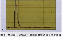
The vibration signal of bearing 11 of a unit was mistakenly tripped. Refer to the DCS record: Absolute vibration value of the shaft began to increase significantly until it exceeded the high II value 4 minutes before the trip; Absolute vibration of the shaft within 4 minutes after the unit tripped. The peak value once appeared 500μm and oscillated sharply; when the rotational speed dropped to 2420r/min, the oscillation disappeared and the fluctuation continued to exist, but the relevant parameters did not change during the above time period. Wuxi Wensheng Automation Instrumentation Co., Ltd. 
The reason why the absolute vibration signal causes the protection system to have a high probability of malfunction is that the absolute vibration (represented by the speed) needs to be converted into the required displacement signal after an integral. Take Wuxi Wensheng Automation's product as an example, and its conversion formula is:
D=1000V/3.14f
Where D is the displacement (peak), mm;
Wuxi Wensheng As the integration process, the speed signal will be affected by the frequency-dependent gain, low-frequency gain, high-frequency gain. When the speed probe suffers from low-frequency interference, it may affect the sudden change of the output signal. After compounding, a large absolute vibration false signal will be output, which increases the probability of a malfunction.
1.2 Measuring components (vibration speed sensor) failures Most of these failure phenomena are manifested as sudden changes in the signal, but the results of different units are affected. For example, the y-direction vibration signal of the No. 4 bearing of a 300MW unit suddenly jumps above the set value of the protection action (high The II value) results in shutdown (see Figure 1). No abnormalities were found after the inspection. After replacing the Wuxi Wensheng Automation Eddy Current Probe and the preamplifier, the system returned to normal. 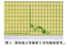
During the turn-over process of another 600 MW unit, the vibration signal of the Y-bearing bearing of No. 6 bearing suddenly increased from 30 μm to the alarm setting value (high II value), and remained cyclically fluctuating between 60 μm and 80 μm after shutdown (see Figure 2). . Replace the card, the front device, and the extension cable one by one, eliminate the end of the fluctuation, and return to normal after replacing the probe. 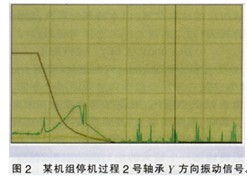
1.3 Earthing of the vibration monitor and cable protection are not standardized. Different ground networks will produce a potential difference, which will generate a circulating current in the shielding layer. Overlaying on the signal will cause analog fluctuations or abrupt changes. Therefore, reliable grounding and cable protection measures are very effective in suppressing interference. Important, many facts in the statistics demonstrate this:
When a unit is running at 750MW, the vibration of No. 3 tile continues to jump because the shielded cable is not grounded;
When the booster fan of a desulfurization system is shut down, the vibration signal will jump even higher than the value of II, due to the fact that the grounding of the cabinet is measured to be ground-welded;
During the infrastructure commissioning phase of a 600MW unit, the desulfurization booster fan trips due to the vibration signal jump. After the simulation test, the welding machine is welded near the TSI measuring cabinet. The cabinet is located between the grounding point of the welding machine and the welding point, and the cabinet is grounded during welding. After the potential difference generated on the wire is coupled into the signal line through the electric field, the card and the front device are damaged;
The vibration signal jump of No. 4 bearing of a 600MW unit and the jump of the turbine speed signal of a 30OMW unit cause the unit to trip, respectively. The cause of the investigation was that the connection cable was not properly protected during installation and installation, and the shield layer was worn out due to vibration and other reasons. Caused by 2 or more grounding.
For TSI systems, probes, extension cables, and preamplifiers, the three are a single measurement and have corresponding impedance and characteristic curves. Once they change due to external factors, they can also cause signal anomalies. If the vibration signal of the Y direction of No. 8 bearing fluctuates during operation of a unit, the reason is that there is an impurity in the joint of the front device connecting the extension cable.
During the operation of a unit, the No. 3 bearing has a high vibration II signal and mistakenly sends a trip. Checking the protection logic is based on the relative vibration of the bearing. The X-to-high II signal and the Y-to-high II signal form an AND logic. Stopped. However, the output of the inspection device is set to "locked" (manual reset required after the signal disappears), and then the historical record is checked. It was found that the Y-absolute vibration signal of the No. 3 bearing reached the high II value one month ago, and was not held because the output signal was not reset. When the No. 3 bearing X fails to the relative vibration channel, the "AND" logic condition is satisfied causing the tripping machine.
1.5 The protection setting is too large The domestic bearing group vibration signal of the turbine of the generating group is uniformly designed to have a high II value of 125 μm and a high II value of 25 Oμm. The device does not play a protective role when there are many turbine body anomalies. For example, when a 600MW unit is running, the vibration signal mutates. The vibration data analysis determines that something is flying. After checking the bolt cover of the middle-low backrest wheel, the maximum value of the vibration has just reached the high II value. When another 600 MW unit was operating at 358 MW load, the vibration signal of the low pressure rotor was significantly increased after the unit restarted due to the boiler. At that time, dynamic balance processing was performed. After the maintenance of the unit after 1a, it was found that the low-pressure rotor shroud fly off severely, in which the third-stage rotor blade of the low-pressure rotor was damaged or detached in multiple stages, but the vibration value of the abnormal condition was far from the high 1 value.
1.6 Power system is not redundant The TSI system that is still in the organic group is still powered by a single power supply, or the power module is still single although the dual power supply is used. Although there have been no cases where the TSl system is paralyzed due to power loss, single-supply power supply is always a security risk.